@semprelibera
2020-01-31T07:01:32.000000Z
字数 6149
阅读 1237
结构力学作业-令和2年1月24日
assignment
Problem 1. About bucking of steel members during seismic retrofitting
Steel members in structures like buildings or bridges are usually made of thin plates, and it is well-known in mechanics that slender members in compression are susceptible to bucking, either global bucking or local bucking. The basic mechanic intuition is that wherever there is compressoin stress, there is a risk of bucking. Buckings are generally divided as two categories: global bucking and local bucking.
Prevent bucking of members under compression.
A) Global bucking
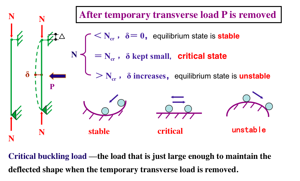
- Bucking of a column under compressing is a prototype of global bucking. (See the figure below.) The critical load for the Euler column with two pinned ends is
The critical load for columns with different boundary conditions can be calculated using the notion of effective length factor, which is 2 for free-end column, 0.5 for fixed-fixed column and 0.7 for fixed-pinned column. Thus, in order to increase the stability of a column under compression, it is useful to change its boundary condition, making the effective length shorter. In addtion, it is also crucial to control the slenderness of the column.
- Bucking of a Euler column is a flexural buckling since the stiffness resisted to the bucking is bending stiffness. In addition to flexural bucking, a column can also has torison buckling and flexural-torional buckling. Columns with different cross-section have different tendency for different mode. So it is also useful to consider changing the form of the cross section to increase the stability of the column.
B) Local bucking
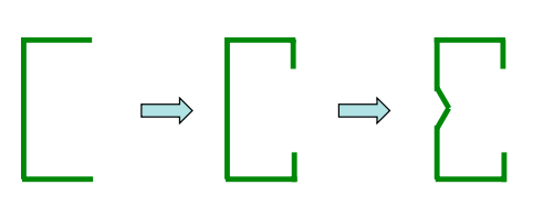
As mentioned above, the steel member usually consists of several thin plates, with some internal and supported while others outstand and un-supported. These thin plates with compression stress under load are prone to warping, known as local bucking. Plate buckling may be avoided by limiting the width- to-thickness ratio of compression plate elements within the cross section. The stronger the constraint, the larger the local buckling factor. (See figure below, with the change of constraints, the local stability improves.)
Prevent bucking of members under bending.
A) Global bucking
For a bending member, one important mode of global bucking is the lateral torional bucking, as known as out-of-plane bucking. (See the figure below.)
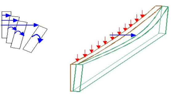
The detailed analysis of a bending member is quite complicated, but the basic idea is that compression stress in the flange is the main reason for global bucking, and the slenderness of the beam should be controlled using lateral support.
B) Local bucking
For flange under compression, and parts of the web under compression, bending and shear, it is possible to have local bucking. The principle is the same as compression member, The stronger the constraint, the larger the local buckling factor. Practical actions to improve local stability of bending members are
1) Modify boundary condition
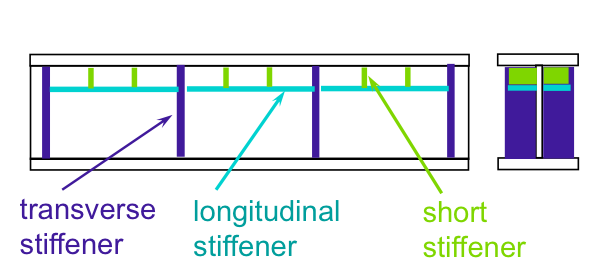
2)Decrease width-to-thickness ratio, including increase thickness or setup stiffeners (See figure below). Stiffeners are often a better choice since usually the thickness of steel plates should not be too large.
Problem 2. Treatments of fatigue damage in steel plates
Fatigue damage in steel plates are usually due to initial microscopic cracks propagating through the plate. By definition, fatigue is the formation of a crack due to cyclic service loads[1]. Fatigue may lead to fracture of the member of a strucuture, which might be very dangerous because fracture often happens suddenly without any sign of failure. Thus, it is crucial to conduct rehabilitation and retrofit of steel plates with fatigue damage.
A rehabilitation is to prevent the propagation of a fatigue crack, while a retrofit is intended to futher improve the fatigue resistence. Rehabilitation and retrofit techniques have three major categories: 1) surface treatments, 2) repair of through-thickness cracks, and 3) modification of the connection or the global structure to reduce the cause of cracking. Here, we only discuss one particular method in the first category: impact treatments.[2]
Impact treatments involve with improving the surface of weld toe surface of steel plates. The weld is the weakest part of steel members, where most of the cracks initiates. Impact treatments introduces compressive residual stress near the weld toe to close the cracks and prevent further propagation of defects. The most effective way to conduct impact treatment is to work under dead load, so that the effect of impact treatment only need to overcome the tensor stress caused by the live load. Impact treatments are best suited as retrofit techniques. One very effective technique to conduct impact treatment is callel Ultrasonic Impact Treatment (UIT), which employes low-amplitude (20-50 microns), high-frequency displacements (27-55 kHz) ultrasonic wave. UIT has proven more effective than hammer peening at improving the fatigue performance of welded joints, so it can be assumed that UIT will increase the fatigue strength of cover plate details and transverse stiffeners by at least one detail category.[3][4]
Problem 3. Solve a differential equation
Solve the following differential equation (DE)
This is an inhomogenous linear DE with constant coefficient. The solution of this DE is the sum of the solution of the corresponding homogenous DE with one particular soltuion
The corresponding homogenous DE is
The characteristic polynomial of this DE is , with root . So the nature angular frequency of the system is and the homogenous DE has two independent solutions and . Thus the homogenous solution is the linear combination of this two bases
where are two arbitrary real coefficients. The particular solution is a little bit trickier, since the frequence of the excitation hits the natural frequency of the system and the resonance will happen. The system has zero damping, so it is a pure resonance. We apply the exponential response formula
where the notation means the imaginary part of a complex number. Notice this particular solution grows with with no bound, as is expected in the case of pure resonance. It can be immediately check that satisfies the original inhomogenous DE. As a result, the solution can be written as
[1] Maddox, Stephen John. Fatigue strength of welded structures. Woodhead publishing, 2014. ↩
[2] Dexter, Robert J., and Justin M. Ocel. Manual for repair and retrofit of fatigue cracks in steel bridges. No. FHWA-IF-13-020. United States. Federal Highway Administration, 2013. ↩
[3] Tryfyakov, V. I., et al. Ultrasonic impact peening treatment of welds and its effect on fatigue resistance in air and seawater. Offshore Technology Conference. Offshore Technology Conference, 1993. ↩
[4] Roy, Sougata, John W. Fisher, and Ben T. Yen. Fatigue resistance of welded details enhanced by ultrasonic impact treatment (UIT). International Journal of Fatigue 25.9-11 (2003): 1239-1247. ↩
